Superstructure Construction Part I
The kit comes with a large, single-piece fiberglass part representing the main, 01, and 02 decks. I was not very happy with the wall thickness of the part so decided
to scratchbuild my own superstructure. First I created 3D models of each deckhouse and each deck in Solidworks. I based these models on dimensioned drawings where possible, followed by
undimensioned drawings and photos where required.
For each deckhouse, I created frameworks based on 0.375" x 0.125" cross-section that formed footers and headers. I broke these parts into manageable sections and printed
them in ABS. I then built the deckhouse structures using 0.060" x 0.250" styrene "studs" between the headers/footers. By carefully aligning everything, this yielded an extremely
accurate framework for each deckhouse.
Next I sheeted each bulkhead with 0.030" styrene, except in areas with very tight curves, where I used 0.015" sheeting. When each deckhouse structure was complete, I printed
the outline of the associated deck, laid this on 0.040" styrene, and carefully cut the deck out by hand. Each deck was carefully aligned to the deckhouse below it and
attached using Bondene solvent cement. Since my plan is to add interior detail in certain areas, I wanted to keep each deck assembly a separate piece (for now).
Finally, I approached the issue of structural rigidity by cutting a 1/8" sheet of plexiglass such that it underlaps the bottom of the maindeck deckhouse by 0.1875" (half the
width of the footer). Once I was satisfied with this shape, I traced it onto the maindeck pieces on the hull and cut them to shape. I then added a 2-inch tall longitudinal
stiffener to the baseplate, and glued this assembly to the maindeck deckhouse using SciGrip #4 for a solid bond between the acrylic / ABS joint. This design yields a
superstructure assembly that:
- when held at one end (and this thing is 38-inches long) exhibits no flexing or twisting whatsoever
- weighs 3 ounces less than the comparable fiberglass part, and
- literally "clicks" into place on the maindeck.
Use the (vertical) scrollbar at right as needed. Clicking on any thumbnail will take you to a larger version of the photo.
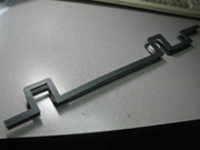 |
This is a header/footer pair from the maindeck deckhouse. These parts were printed on a 3D printer: while the surface finish is not suitable for visible
components, they are extremely accurate (less than 0.007") and ABS has a great strength:weight ratio. |
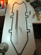 |
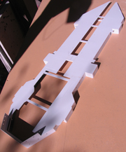
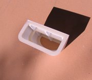
This is the footer for the maindeck deckhouse with studs installed. You can get a sense of size - that is a 24-inch scale sitting inside the part. |
| |
|
|
|
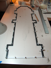 |
This is the O1 deck footer with studs installed. The rear of this part is trucated because this area of the ship has a two-deck tall bulkhead. This bulkhead
will be attached to the maindeck for a seamless appearance (see photos below for better explanation). |
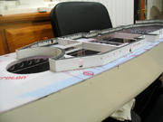 |
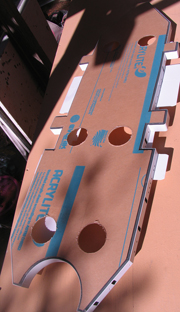
Here is the maindeck deckhouse fully sheeted with 0.030" styrene. One advantage to this type of structure over the fiberglass part is a more in-scale
wall thickness, which in turn yields a much more realistic appearance at portlights and hatches. |
| |
|
|
|
 |
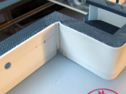
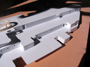
This is the aft end of the maindeck, showing the area where the bulkhead is two decks tall. I cut the framework from the O1 deck and used it here. |
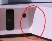 |
This is an example of improvements which can be made over the fiberglass part. On the actual ship the two forward maindeck 5-inch handling rooms
actually sit just outside the maindeck house bulkhead, and are "attached" to the house via fairings, leaving the inner rounded corners visible. |
| |
|
|
|
 |
Another view of the faired area on the 5-inch handling room... (didn't notice the blurry pic until too late). |
 |
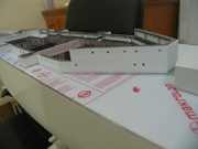
This is the "completed" maindeck deckhouse, O1 deck, and baseplate. |
| |
|
|
|
 |
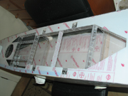
The underside of the maindeck assembly, showing the baseplate (with protective paper still attached to acrylic sheet). |
 |
This is the O1 deck house and O2 deck. Again, this assembly contains a section of double-high bulkhead, this time at the forward end. |
| |
|
|
|
 |
This is the underside of the O1-deck deckhouse. |
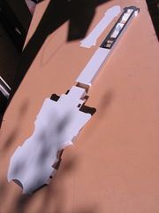 |
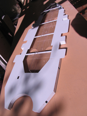
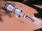
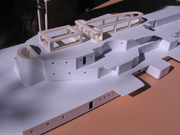
O2 deck house with O3 deck installed. I've always thought this part of the ship looks like a guitar... The expansion joint at Frame 115
runs right across where I wanted to separate these two pieces (the forward part of the covered passageway). In the aft section you can see the initial pieces of some
interior detail which is visible through the open archways aft of the triple 40mm towers. |
| |
|
|
|
 |
The underside of the O2 deck house. |
 |
This view shows the cutout in the maindeck pieces. The superstructure baseplate fits into this opening. |
| |
|
|
|
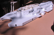 |
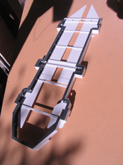
This view shows the main through O2 decks assembled (actually they are simply nested on each other). |
 |
Rear view of same part. |
| |
|
|
|
| |
|
|
|
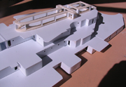 |
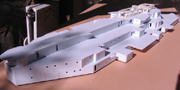
Close-up of the forward portion of the assembly. |
 |
Another view. You can see that given the accuracy of the framework, a very minimal amount of filler and rework is required. |
| |
|
|
|
 |
Close-up of the after portion of the assembly. |
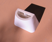 |
Finally, here is a view of the conning tower support. This was created - again starting from a 3D model - by printing three internal
"decks" and sheeting with 0.015" styrene, yielding a very light and durable assembly. |
| |
|
|
|
 |
Underside of the conning tower foundation. |
|
|