16" Turret and Mk38 GFCS Director Mechanism - Construction (part 2)
Barrel Elevation Mechanism
With the turret training mechanism in-hand, I turned to the gun barrel elevation works. Conceptually similar to the former, the challenges involved here include
a much more compact mechanical envelope - everything must be housed within the turret - and a reduced range of motion (-2 to +45 degrees vs. -150 to +150 degrees).
The rotational rate of the barrels is actually 3x that of the turret, so obtaining the proper speed without the use of a large (84-tooth) gear should be achievable.
The next challenge was connecting the drive train to the barrels themselves. The Missouri kit comes with something I'll refer to as the "trunnion block." It is
essentially an oddly-shaped chunk of resin with three holes for the barrels. Sadly, the trunnion blocks in my kit are so badly warped that the barrels are anti-parallel
by almost 1/4" over their length. So... I modeled a new part in Solidworks that incorporates a 90-degree portion of a 40-tooth gear and printed three of them. Problem
solved.
Use the (vertical) scrollbar at right as needed. Clicking on any thumbnail will take you to a larger version of the photo.
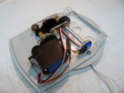 |
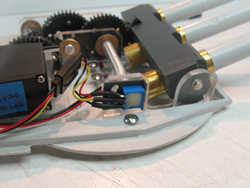
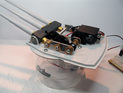
Gunhouse mounting plate showing the servo and geartrain. I again used 1/4" aluminum shafts and flanged bronze bushings.
The bearing and servo mounts are in 1/8" acrylic. The light grey piece is the kit-supplied turret floor. Since the final drive gear and the 90-degree gear mounted
to the trunnion block are the same tooth-count, they turn at the same rate: therefore the position sensor is mounted to the secondary shaft as shown. |
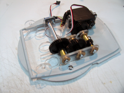 |
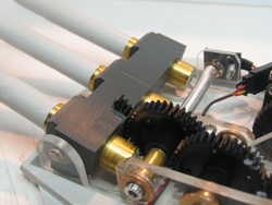
Different view of the same assembly, showing the geartrain to better effect. There are 3x [16:40] gearsets, for a final reduction
ratio of 15.6:1. |
| |
|
|
|
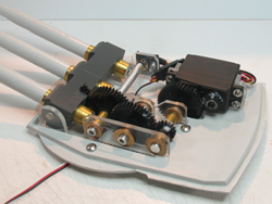 |
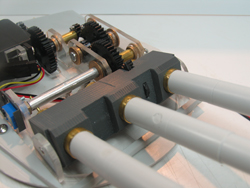
This is the completed assembly with trunnion block and barrels installed. |
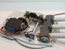 |
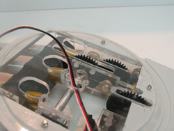
Opposite view of same completed assembly. The position sensor is connected to the secondary shaft in the same manner
used in the barbette, and is wired into the servo through a standard Futaba connector purchased at ServoCity.com. |
| |
|
|
|
 |
This is a closeup of the position sensor showing the slotted adjustment plate (grey 3D-printed piece). The plate
attaches to the bearing mount and allows fine adjustment of the sensor position to align the barrels with "zero degrees" elevation. I used a 1/8" precision
steel shaft for the trunnion axle, also purchased at ServoCity. |
 |
Closeup of the trunnion block with the 90-degree 40-tooth gear installed. The position of this gear "portion"
is critical in that it must be perfectly concentric with the trunnion axle: Solidworks design and 3D printing guaranteed a perfect alignment. |
| |
|
|
|
 |
Front view of the trunnion block. I created the gear portion by carefully cutting a new 40-tooth delrin gear on a jigsaw.
You can see the remainder of its hub sticking thru the front of the block. |
 |
Underside of the elevation mechanism. Due to the cramped quarters, the large gears extend below thru slots cut in the mounting
plate. The servo harness passes thru the hole as shown, then into a similar hole cut in the 84-tooth final drive gear in the training mechanism. |
| |
|
|
|
 |
Finally, the completed assembly. |
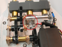 |
Red-circled area shows the mount point between the turret and barbette. The aluminum hub (which is connected to the final
drive gear in the barbette) accepts 4x 6-32 screws from the gunhouse, and oila' - done! |
| |
|
|
|
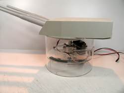 |
With the kit's gunhouse installed. Substantial carving of internal webbing was required for a clean fit. But, the design meets
all my established criteria, and I'm pretty happy with it Now I just have to control it! See next part for that. |
|
|
| |
|
|
|