Hull Maindeck - Wood decking installation, bow section
(scroll down to view entire page)
Missouri's main deck aft of the focs'l was built with 5-inch wide teak planks overlayed on the steel deck. If you are wondering why, there are many reasons floating
around the 'Net, and I have no way of knowing which one or ones is/are accurate. So I'll let you do your own homework and draw your own conclusions. The planks run
parallel to the centerline. "Margin planks" are installed around the inner and outer perimeter of the "field" of planks, as well as around any object mounted to the deck
within the field. Basically, whenever a course of planks "ends" it does so at a margin plank.
At smaller field/margin plank intersection angles, a technique called "nibbing" is used at the join. This is done to avoid slender, narrow sections of planks. See the
diagram below for an example of this joinerwork. All seams between planks were caulked, which gives each plank the classic "outline" appearance.
I chose to begin this sub-project (it should really be considered a super-project...) at the bow and work aft. The problem with this is that there are a large
number of "things" installed in this region, which means a correspondingly large number of margin planks need to be fabricated and installed. And this in turn means
a large number of interruptions in a given course of planks. All of which means... lots of time, lots of learning, lots of effort.
I began by ordering lumber from Northeastern Scale Lumber. I specified basswood strips, 1/16"-square for the planks,
and 1/4 x 1/16" for the margins. To simulate the caulking, I used 3M 1080 Wrap Film. This material is available in a wide range of colors (I used flat black), is 0.004"
thick, and has pressure-sensitive adhesive on one side. Once you get used to it, the film is very easy to work with - cuts easily and precisely, stretches around odd shapes,
etc. My plan was to mimic as closely as possible the planking patterns visible in the myriad photos of Missouri. An interesting note: the four ships differ to a significant
degree in decking details. I don't know if this is an as-built feature, or if the ships which have had their decks replaced were victims of less-than-authentic replacement
joinerwork. Regardless, make sure you are using photos of the correct prototype for your deck :)
I laid out the margins surrounding the windlasses and chain guides, and quickly realized there was something wrong. By studying photos and armed with the knowledge that the
planks are five-inches wide, it is possible to estimate the size of some of the margin planks visible in photos. By reconciling this information with that of known dimensions,
I realized there were errors for which I could not account. I finally realized the oversized planks I was using (0.0625" plank + 0.004" caulk = 0.067" or 6-3/8" plank widths)
were the cause. Of course, this revelation occurred after approximately 20-hours were expended. So... I stripped off all that work and ordered new lumber. This time I chose
3/64" x 0.040" strips. Since 3/64 = 0.047", adding the caulking brings this up to 0.051" or just under 5-scale inches: perfect if you take into account variances in the lumber
(more on that later). Note that this new size planking represents a 25% decrease in width from the original 0.0625" lumber - more on that later, too :)
As mentioned, the bow section of decking is rife with margin planks. By starting here, I was immediately on the steepest part of the learning curve, and progress was
very slow. I have no real solution to this, other than to stick to it and break up work sessions with other activities. I found that it usually takes me 5-10 minutes to
"get in the groove." I have completed marathon eight-hour sessions, but need to be aware of when my workmanship quality begins to tail off, and force my self to stop before it
becomes noticeable.
Tools
There are no special tools required for this task, unless like me you have become far-sighted (a polite way of saying I need mild readers to, well, read...). I found that
by using my optivisor over the readers with a 2-diopter lens (1.5x magnification), I can see sufficiently well while still maintaining an adequate depth of field. By setting the
position of the visor just above the readers, I can quickly switch between reader-vision and super-vision by simply changing the angle of my head.
In addition to the optics solution, I use the following tools:
- #1 XACTO handle with #11 blade,
- #2 XACTO handle with a #18 blade,
- #6 XACTO handle with a #2 blade,
- Northwest Shortline Chopper 2, and
- Mitsutoyo 500-series digital calipers (important to maintain alignment!).
Installation
I started by finding and scribing the centerline into the deck. Next I created a lateral grid comprising four lines spaced 0.25" apart, repeated every 2.0". These lines are
used to locate the plank lengths for each course (the planks are 16-feet long, and the ends are offset two-feet on adjacent courses: this pattern repeats every four planks).
Once the grid was established I used the following process:
- cut plank to length, shape each end as necessary (eg., nibbing)
- nib margin(s) as required
- check fit and adjust as necessary to accommodate caulking material
- add caulking material to edges (usually two), ensure none protrudes below bottom edge of plank - top is ok
- check alignment along both axes
- install plank using gapping superglue, and finally
- trim excess caulking material using chisel blade.
As with lots of things, there are additional tricks and techniques you pick up along the way to becoming a Deck Jockey. For reference the currently-completed section
of deck measures approximately 30-inches in length and 12-inches at the widest point.
Use the (vertical) scrollbar at right as needed. Clicking on any thumbnail will take you to a larger version of the photo.
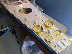 |
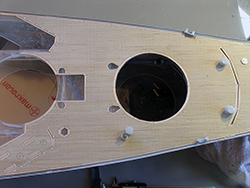
Overall view of completed deck area showing progress as of mid-March 2017. |
 |
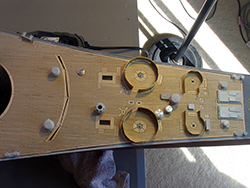
Close-up of forward area showing anchor handling, 20mm and 40mm mounts. |
| |
|
|
|
 |
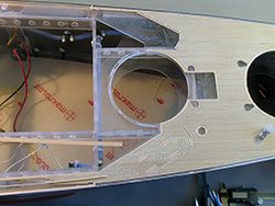
Close-up of mid-section. |
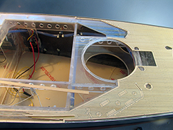 |
Close-up of aftermost completed section, showing fitment around Turret 2 and forward end of superstructure. |
| |
|
|
|
 |
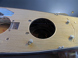
Overhead of forward section. |
 |
Overhead of mid-section. |
| |
|
|
|
 |
Overhead of aft section. |
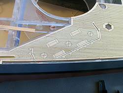 |
Close-up of Frame 70 20mm gallery (starboard side). This shot shows nibbing to good effect. |
| |
|
|
|
 |
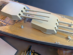
These are requesite shots including the 16-inch turrets for effect. |
 |
|
| |
|
|
|