Mk38 Director Training Mechanism construction (part 3)
As mentioned previously, since the director only needs to train (move along one axis), it is a simpler design. However, given mounting constraints within the
superstructure, the packaging of the mechanism was somewhat of a puzzle/challenge. As before, the requirements for the design are that it mimic the prototype operation,
be easily removable from the model, and be externally indiscernible. Additional constraints include a maximum clearance below the superstructure of one inch (due to the
location of the main drive batteries within the hull), and the remote location of the Mk38 director (roughly 12" above the bottom of the superstructure).
The conceptual model is shown on the intro page to this section, so here I will provide photos of the assembly and how it mounts into the superstructure.
Use the (vertical) scrollbar at right as needed. Clicking on any thumbnail will take you to a larger version of the photo.
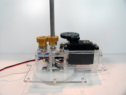 |
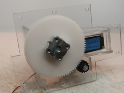
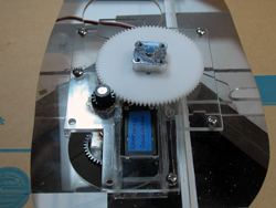
Front view of the mechanism. As you can see, the same basic design elements were used: a main plate with a servo box, two ball bearings
supporting the main output shaft, and a secondary shaft for the intermediate gearing (behind the servo). A major difference here is that I mounted the position sensor offset
from the output shaft: I did this to reduce the amount of components extending below the superstructure baseplate. Doing so required the use of a different potentiometer
and relatively pricey pinion gears (I used these gears rather than the press-on delrin type to aid in future disassembly). |
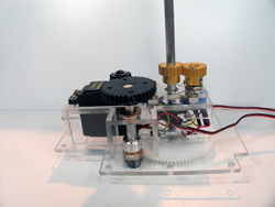 |
Rear view this time. Here you can see the secondary gearshaft and bushings, and the wire harnesses for the servo and position sensor.
I know it looks a little odd, but I placed the large reduction gear below the mounting plate to reduce the amount of cutting on the superstructure support pieces (see below). |
| |
|
|
|
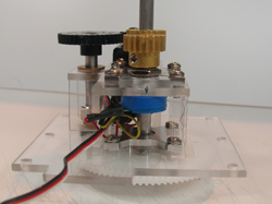 |
Starboard-side view, showing the position sensor and pinion gears. |
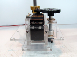 |
Port side, showing the servo mount. The end plate is atached using screws so the servo may be slid out toward the camera: otherwise with
the large intermediate gear in place, I'd never be able to remove the servo. |
| |
|
|
|
 |
Bottom view showing the parts exposed below the superstructure. The entire assembly is held in place with 8x 6-32 screws into the superstructure
baseplate. |
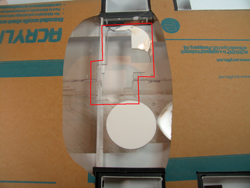 |
Now on to the ugly part: bottom view of baseplate. Since I built the superstructure prior to designing the director mechanism, I hadn't accounted for how it would
mount. Also, to add rigidity to the lightweight structure, I added an internal keel (photo below). I was forced to not only cut a hole in the baseplate, but also thru the keel.
I acknowledge that this is a really messy cut! The white pieces are plugs to fill in holes I made during original construction. |
| |
|
|
|
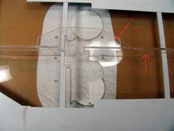 |
Top view of the installation area. Arrow #1 points to the internal keel, while arrow #2 points to the new piece I added to reconnect the fore and
aft pieces, keeping the overall structure flat and rigid (I actually got this idea from the surgeon who recently performed similar surgery on my neck :) ). |
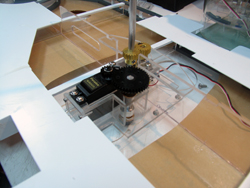 |
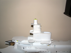
Here's a view of the forward director assembly installed in the superstructure. Hopefully you may now understand why the funky design, and the
odd cutouts. |
| |
|
|
|
 |
This is what protrudes below the baseplate. I'll likely add some protection ribbing so that the superstucture may be safely placed on
a tabletop, etc. But in reality, these gears are pretty tough. |
 |
Finally, a testament to the worth of modeling everything in Solidworks... the output shaft wound up in the exactly correct spot :). |
| |
|
|
|