Main, 01, 02, and 03 decks - planking installation, complete
(scroll down to view entire page)
Good grief. I began the planking effort for this model in mid-November, 2016. The last plank was laid on May 9, 2018 - nearly 18 months later.
I didn't really realize it at the time, but this has been the most ambitous task I have ever undertaken in my model building experience. It tested my skill,
my patience, my eyesight, my persistence, my patience (again and again and again...) - once the job was complete I calculated the number of planks by letting Solidworks compute the planked
area of each deck, and then performing the needed arithmetic. The results are as follows:
- Main deck - 640.4 sq. in.; 5,900 planks
- 01-deck - 223.7 sq. in.; 2,070 planks
- 02-deck - 155.4 sq. in.; 1,439 planks
- 03-deck - 74.3 sq. in.; 688 planks
This yields an approximate total of 10,097 planks.
As for labor hours... this is even more of an approximation. There are four basic "types" of planks:
- margins
- field (basic 2" plank)
- single-end nib
- double-end nib
Each plank gets cut, check fit, sanded as needed, black material cut/applied, trimmed, adhesive applied, and installed. For nibbed planks, the mating
margin must be nibbed as well. Figure 60-seconds for a basic field plank, and maybe 3 minutes for a double-end nib plank (and associated margin).
Then weighting these fastest/slowest cases based on the "population" of each, call it an average of 1.75 minutes per plank. That's 17,670 minutes, or
295 hours, spread over 18 months.
The tools and materials used are quite basic:
- Three x-acto knife handles (two large, one small)
- three custom-shaped x-acto chisel blades for nibbing
- 3M falt-black wrap material
- basswood strips - 0.047 x 0.040" (lots of them: Northeastern Scale Lumber.)
- Chopper II cutting table
- a full bottle of thick cyanoacrylate
The workflow for each plank was:
- cut plank to length
- Check fit: adjust/cut/sand as required
- apply pre-cut strip of black warp material to two edges of new plank
- apply cyanoacryalte to plank
- place into position and hold while glue sets
For nibbed planks, the plank had to be marked in-place to get an accurate fit, then removed and trimmed. Then the nibbed plank was laid over the associated margin
plank, and the custom chisel blades were used to nib the margin. Many planks were nibbed on both ends...
I didn't spend much time over the last 18-months updating this website, so the photos in this section show the completed effort. But I will add some work-in-progress
photos as time permits.
Next up: generating artwork to get the first batch of photoetch parts created.
Use the (vertical) scrollbar at right as needed. Clicking on any thumbnail will take you to a larger version of the photo.
 |
The bow area... this was done a year and a half ago. |
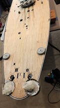 |
The stern. The main deck took a year - virtually to the day - to complete. Unfortunately much of the detail
is aliased-out of this image during resizing: I will have to post a full-resolution image to give a sense of the size (and number of planks!) of this
area. I tried to randomize planks to achieve a prototypical varied appearance: this turned out to be difficult due to tolerances inherent in the wood
planks. Even a width difference of 3-4 thousandths causes a discontinuity in a given run of planks. And if it's not caught immediately, the "ripple effect"
on subsequent runs can be disastrous (can you guess how I know?). |
| |
|
|
|
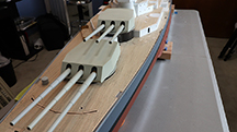 |
The area around T1 and T2. You can see where the (brass) breakwater will be installed. |
 |
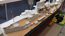
Looking aft on the starboard side, from just forward of the superstructure. |
| |
|
|
|
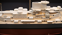 |
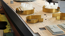
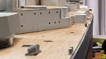
Low-angle view amidships, showing all four planked decks. The unplanked areas are either "waterways" or spaces where steel decking
was left exposed. I have read that the main reason for the planking was to afford protection from falling shell casings. |
 |
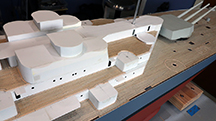
High-angle view of same area. The unplanked rectangular area just above the 5-inch mount is for the flag bag. This area
will be cut out, as the flag bag actually sits down in the deck a few (scale) feet. TEST CAUTION: FULL-RESOLUTION 6MB IMAGE! ( |
| |
|
|
|
 |
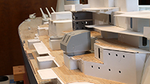
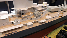
Here is the after portion of the superstructure and the area around T3. |
 |
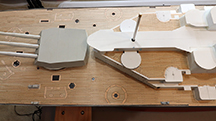
Wide-angle view looking forward from aft of the superstructure. In the lower-left corner of the photo is the margin
planking for a the shield on a 40mm mount. This margin will be "cut down the middle" to allow the shield to sit down into the planking (see photos of the bow
for example). |
| |
|
|
|
 |
Looking forward on the starboard side, from just aft of the superstructure.. |
 |
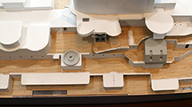
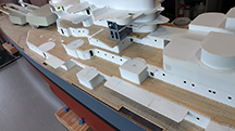
Narrow-angle view looking down at the area around the triple-40mm mount "tower." At the extreme left of the photos is one of
several thru-ways: passageways allowing traversal from one side of the ship to the other while remaining on the weather deck. |
| |
|
|
|
 |
Medium-angle perspective looking forward on the port side. This photo shows all four planked levels. On the maindeck
at the bottom-center of the photo you can see some rectangular inlays - these will contain the support stanchions for the 20mm gallery directly above. There
is another such inlay on the 02 deckabove the 5-inch mount: this will accommodate a two-deck stanchion that supports the ladder decks above. |
 |
Starboard side view of same area. At mid-left you can see directly through the athwartships passageway described
earlier. |
| |
|
|
|