Forward superstructure - to
enclose or not to enclose?
After completing the addition of thicker armor belts to the hull, I decided
to next tackle the forward superstructure. It was at this point that I
learned what I consider to be an extremely interesting facet of modern
battleship design: not only is the hull armored, but there are additional
armored structures throughout the ship designed to increase survivability
against specific weaponry. The most significant of these structures (in
the case of Iowa-class ships) is the "citadel," which is essentially a
blockhouse within the hull and encompassing the main machinery and fire control
spaces.
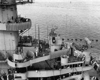 An adjunct to this space is the conning tower, an armored vertical cylinder
located at the forward end of the superstructure, just aft of Turret 2.
You can clearly see this tower at the far right side of the photo at left (note:
as with nearly every photo in this writeup, clicking on the picture will open a
larger version of the photo - use your browser's "back" button to return to the
current page). Also in this photo it is possible to see an open
hatch leading to the interior of the tower: note the (16") armor thickness of
this hatch.
An adjunct to this space is the conning tower, an armored vertical cylinder
located at the forward end of the superstructure, just aft of Turret 2.
You can clearly see this tower at the far right side of the photo at left (note:
as with nearly every photo in this writeup, clicking on the picture will open a
larger version of the photo - use your browser's "back" button to return to the
current page). Also in this photo it is possible to see an open
hatch leading to the interior of the tower: note the (16") armor thickness of
this hatch.
Why is any of this pertinent to this stage of the construction process?
Iowa-class ships were originally designed with a conning tower as shown in this
photo, and Iowa was actually completed in this configuration. However, by
the time New Jersey was completed, it was decided to add an additional enclosed
deck structure surrounding the bridge level of the conning tower.
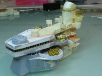
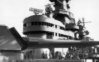 The photo at left shows this structure as added to New Jersey during
post-shakedown refit. This style bridge is commonly referred to as the
"round bridge," and New Jersey is the one ship of the class to have carried this
style.
The photo at left shows this structure as added to New Jersey during
post-shakedown refit. This style bridge is commonly referred to as the
"round bridge," and New Jersey is the one ship of the class to have carried this
style.
The plot thickens...
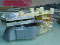
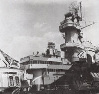 By the time Missouri and Wisconsin were completed, the design of the enclosed
bridge had again been revised, this time to the roomier "square bridge" as shown
at left. Ultimately, all four ships in the class were upgraded to this
style bridge.
By the time Missouri and Wisconsin were completed, the design of the enclosed
bridge had again been revised, this time to the roomier "square bridge" as shown
at left. Ultimately, all four ships in the class were upgraded to this
style bridge.
Information available on Montana indicates that she was originally designed
with a tower similar to that on Iowa as-built: ie., with no bridge enclosure.
But this makes sense, since the plans for Montana were drawn up while Iowa was
being built, and the designers would have borrowed as many existing design
elements as possible. Speculation: In all likelihood Montana
would have carried the square bridge enclosure for several reasons: practical
experience with Iowa had proven the design as an upgrade to the original and, by
the time Montana's construction would have been complete, all four Iowas had
this bridge installed. The Yankee Modelworks kit seems to be faithful to
the original design plans in that it models the conning tower with no bridge
enclosure. However, I personally don't like the look of this style, and
feel the square bridge yields a much more purposeful and commanding appearance
to the ship overall. So it is at this phase of the model's construction
that I ran into my first "what if" decision point: I had (at least) three bridge
styles to choose from, and since the kit represents the configuration I liked
least, whatever I chose would have to be scratch-built.
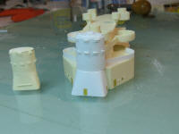
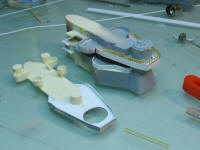
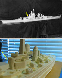 The image at left shows both an early model built during the design process (and
culled from the Web), and the components of the Yankee Modelworks forward
superstructure. In each photo an arrow has been added showing the conning
tower sans enclosure. While it is tempting to use the existence of this
BuShip model as "proof" of what Montana would have looked like, the reality is
such models rarely represent the finished product: even "final plans" are
changed many times throughout the construction process, especially in such a
large project as a capital ship.
The image at left shows both an early model built during the design process (and
culled from the Web), and the components of the Yankee Modelworks forward
superstructure. In each photo an arrow has been added showing the conning
tower sans enclosure. While it is tempting to use the existence of this
BuShip model as "proof" of what Montana would have looked like, the reality is
such models rarely represent the finished product: even "final plans" are
changed many times throughout the construction process, especially in such a
large project as a capital ship.
So.... what to do? The answer turned out to be not so simple.
Planning stage
My first step toward a solution was to model all major components of
the kit's superstructures in a 3D CAD program (in this case, AutoCAD). This
would allow me to make "virtual modifications" so I could evaluate how the
changes looked, and whether they would at least make some sort of sense from a
real-world design perspective. After carefully measuring each component
and building it in the CAD program, I then created an enclosed square bridge
structure to see how it would integrate into the existing kit pieces. The
result is shown in the screen shot below.
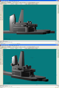
 This process led to a disturbing discovery: the kit-supplied conning tower was one
deck too short for integration of an enclosed bridge ala Iowa. This
observation became even more apparent when stacking the YMW parts up against
those from a Tamiya Missouri kit. And since the conning tower is part of
the 01/02 deck "block" (see above photo), that meant I'd have to do some
irreversible surgery in order to proceed with my plan. Not to mention scratchbuilding a new conning tower and forward fairing. It was beginning
to feel like every time I came up with a solution, I was increasing the
workload by double the amount ("one step forward, two steps back...").
This process led to a disturbing discovery: the kit-supplied conning tower was one
deck too short for integration of an enclosed bridge ala Iowa. This
observation became even more apparent when stacking the YMW parts up against
those from a Tamiya Missouri kit. And since the conning tower is part of
the 01/02 deck "block" (see above photo), that meant I'd have to do some
irreversible surgery in order to proceed with my plan. Not to mention scratchbuilding a new conning tower and forward fairing. It was beginning
to feel like every time I came up with a solution, I was increasing the
workload by double the amount ("one step forward, two steps back...").
So, I finalized some plans for both a new conning tower and enclosed bridge
structure, taking into account how best to integrate these parts into the kit
resin, and began cutting styrene. The result was a new conning tower as
shown at right. Notice how this new tower stacks up to the original
kit-supplied part - it wound up being substantially taller.
First attempt
 Now that I had the new conning tower built up, it was time to construct the enclosed
bridge deck - you know, the part that led me to this point in the first place?
I removed material from the decks per plan, and grafted in the new styrene, with
the end result as shown here. Note that I built the window frames out of 0.020"
square stock. After sitting back and looking at
the whole thing, I decided I didn't like the "inset" appearance of the frames
(they are attached to the inside edge of the upper/lower bulwarks), so I looked
for an alternative solution.
That solution wound up consisting of some
photo-etched ladders from my Nichimo 1/200 Yamato set from GMM - these parts
scale out almost exactly to what I was looking for. So, off comes the
enclosed bridge, followed by a new one as shown here. This was a much more
acceptable result.
Now that I had the new conning tower built up, it was time to construct the enclosed
bridge deck - you know, the part that led me to this point in the first place?
I removed material from the decks per plan, and grafted in the new styrene, with
the end result as shown here. Note that I built the window frames out of 0.020"
square stock. After sitting back and looking at
the whole thing, I decided I didn't like the "inset" appearance of the frames
(they are attached to the inside edge of the upper/lower bulwarks), so I looked
for an alternative solution.
That solution wound up consisting of some
photo-etched ladders from my Nichimo 1/200 Yamato set from GMM - these parts
scale out almost exactly to what I was looking for. So, off comes the
enclosed bridge, followed by a new one as shown here. This was a much more
acceptable result.
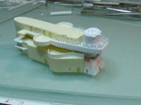
 Now that I had a reasonable solution to the Enclosed Bridge dilemma, I moved
on to the rest of the forward superstructure. Assembly here consists
mostly of stacking the 01/02 deck piece with those for the 04 and 05 decks,
followed by the forward stack. At this point I must interject a subjective
comment about the YMW kit parts. Politely, these parts are substandard,
and borderline unacceptable. The castings themselves were not plumb or
square. In fact the forward superstructure was off vertically by
more than a tenth of an inch from front to rear (a span of only about three
inches). The after portion of these components form the base of the
forward stack, and should be a monolithic structure. But the castings
themselves were so poorly done as to result in massive gaps between decks,
requiring excessive amounts of filler. Finally, the surface detail was
inconsistent in crispness, alignment, and even depth. I removed all the
molded-on hatches in favor of PE parts, but stopped there: anything else would
mean basically throwing the parts away, and I wasn't (yet) willing to do that
with a $500+ model.
Now that I had a reasonable solution to the Enclosed Bridge dilemma, I moved
on to the rest of the forward superstructure. Assembly here consists
mostly of stacking the 01/02 deck piece with those for the 04 and 05 decks,
followed by the forward stack. At this point I must interject a subjective
comment about the YMW kit parts. Politely, these parts are substandard,
and borderline unacceptable. The castings themselves were not plumb or
square. In fact the forward superstructure was off vertically by
more than a tenth of an inch from front to rear (a span of only about three
inches). The after portion of these components form the base of the
forward stack, and should be a monolithic structure. But the castings
themselves were so poorly done as to result in massive gaps between decks,
requiring excessive amounts of filler. Finally, the surface detail was
inconsistent in crispness, alignment, and even depth. I removed all the
molded-on hatches in favor of PE parts, but stopped there: anything else would
mean basically throwing the parts away, and I wasn't (yet) willing to do that
with a $500+ model.
At this point, I've got the forward superstructure assembled and adequately
filled: I have the new conning tower installed, and the enclosed bridge deck
(the second one) is in place. I have replaced a minor amount of surface
detail with scratch-built parts, and added some PE hatches and railings.
Next up: addition of some of the white-metal parts from the kit, specifically
the flag bags and 40mm mounts. Enter my next major disappointment.
Flag Bags
 The photo at left shows the kit-supplied white metal flag bag (down on the work
surface), and the scratchbuilt version up on deck. After spending an
inordinate amount of time cleaning up the kit part, there quite simply was
nothing left save for a blob of metal. No detail, nothing resembling an
actual flag bag. So I threw them out and built my own. Again, not
something I was expecting for a kit in this price range.
The photo at left shows the kit-supplied white metal flag bag (down on the work
surface), and the scratchbuilt version up on deck. After spending an
inordinate amount of time cleaning up the kit part, there quite simply was
nothing left save for a blob of metal. No detail, nothing resembling an
actual flag bag. So I threw them out and built my own. Again, not
something I was expecting for a kit in this price range.
40mm gun mounts
I guess it's fairly common in the ship modeling world to expect to replace
kit gun mounts with aftermarket parts, and so that is what I did. YMW's
40mm guns are white metal blobs with nice injection plastic barrels.
Doesn't make much sense to me to put nice barrels on mounts that are nothing
more than blobs, so the entire thing went in the trash. I initially
purchased one package each from LionRoar and L'Arsenal, and after building two
of each, L'Arsenal's offering wins hands down. The parts are easier to
assemble (the brass used in the LionRoar kits are disturbingly flimsy) and the
3d resin barrels make all the difference in the world. *HIGHLY*
recommended.
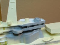
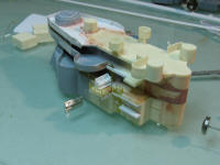
 Once I had a 40mm mount to play with, I soon realized that the addition of the
enclosed bridge left insufficient room in the forward 40mm gun tub - the new
bridge deck overhang too far into the tub area (see photo above).
Solution? Cantilever new tubs further outboard on the existing structure
(one step forward...). Compare the photo at left with the one above: note
the modified forward gun tub.
Once I had a 40mm mount to play with, I soon realized that the addition of the
enclosed bridge left insufficient room in the forward 40mm gun tub - the new
bridge deck overhang too far into the tub area (see photo above).
Solution? Cantilever new tubs further outboard on the existing structure
(one step forward...). Compare the photo at left with the one above: note
the modified forward gun tub.
I'm one of those people who doesn't do so well with repetitive tasks, so
after scratchbuilding both flag bags and 6x 400 mounts, I added some structural
detailing to the underside of the bridge deck and extended gun tubs, then
decided it was time to turn my attention elsewhere - in this case, to the after
superstructure.